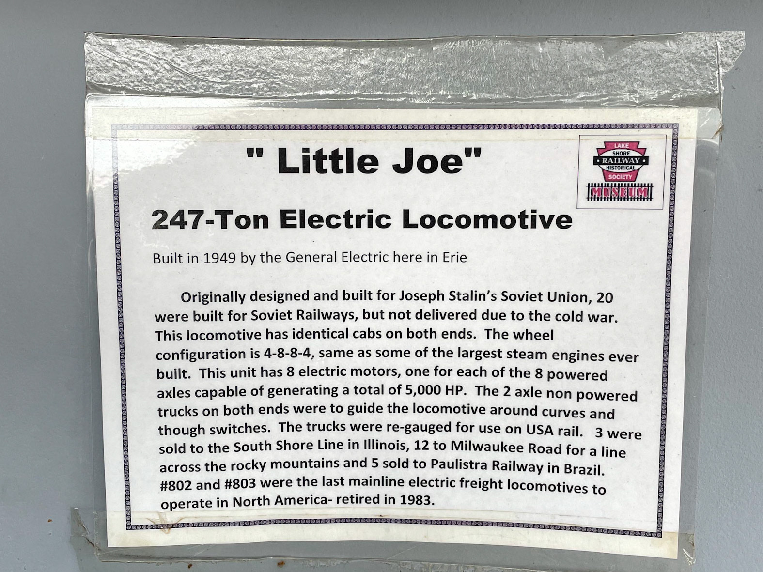
Specifications:
Wheel arrangement: 2-D+D-2, eight powered axles
South Shore = 1,200v D.C. HP: 5,100 - Milwaukee Road = 1,500v D.C. HP: 5,500
Tractive effort: 77,000 lbs @ 22.5 m.p.h.
Length 87'-9-3/4"
Weight: 545,600 lbs.
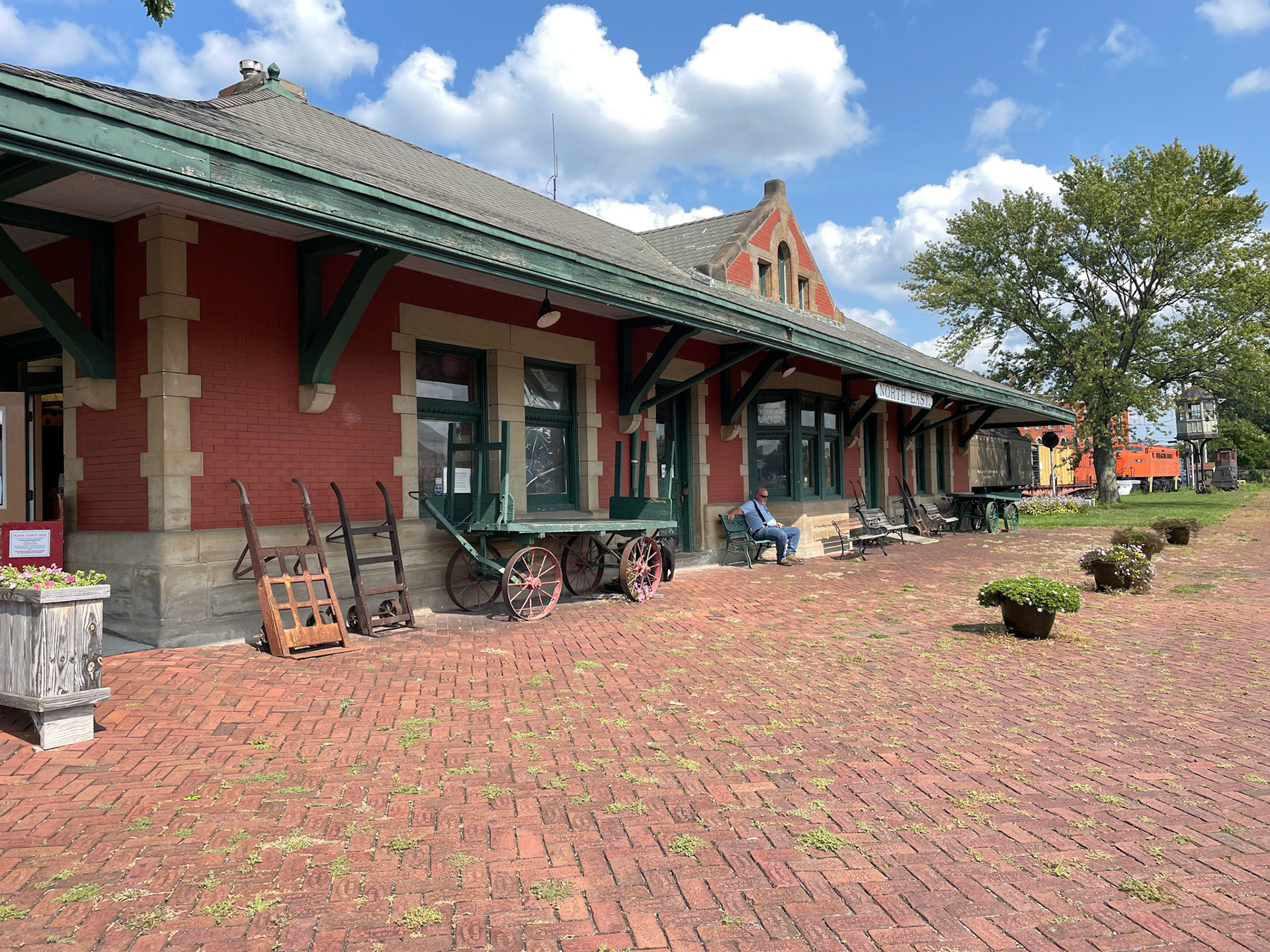
Lake Shore Rwy. Museum in the NYC depot at Nort east, Pa.
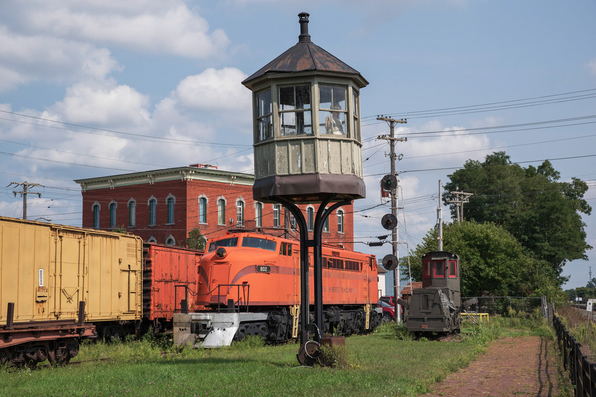
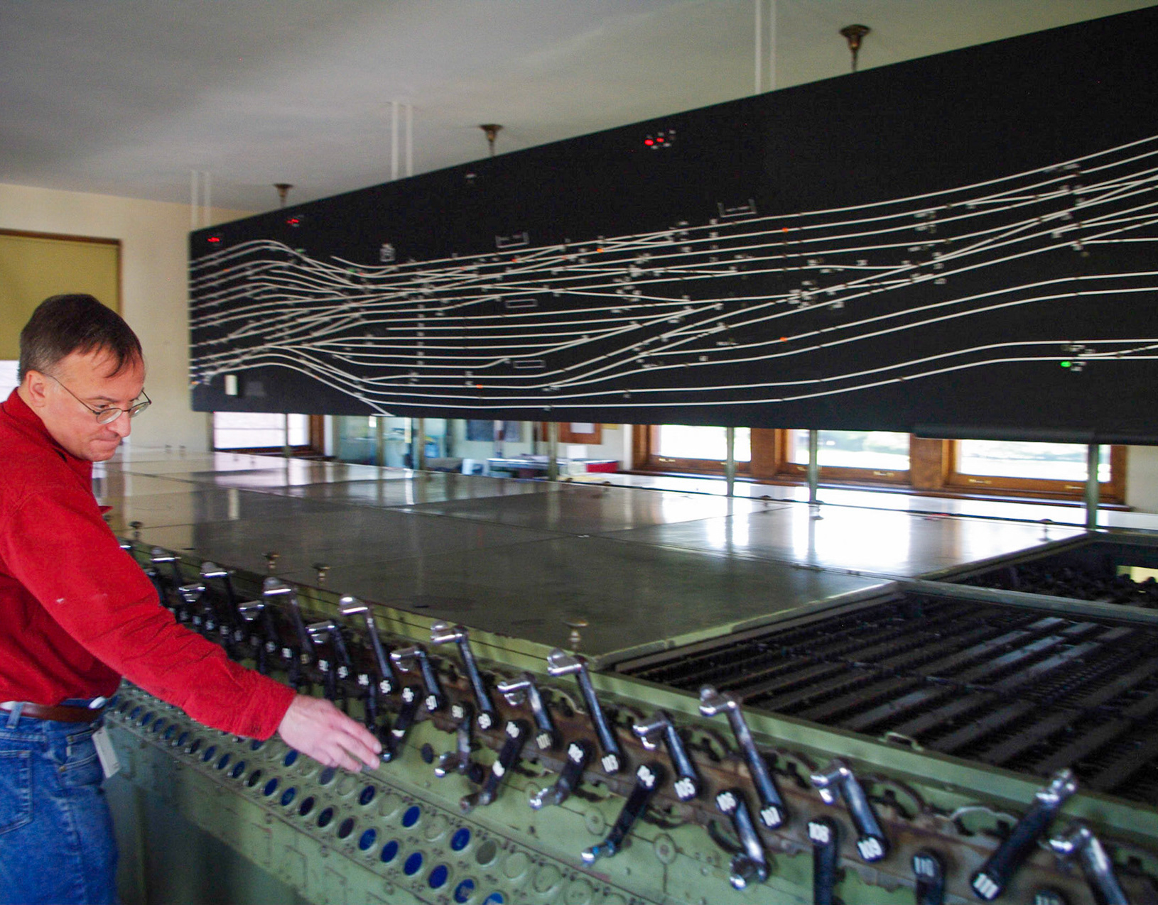
Signal tower and Little Joe
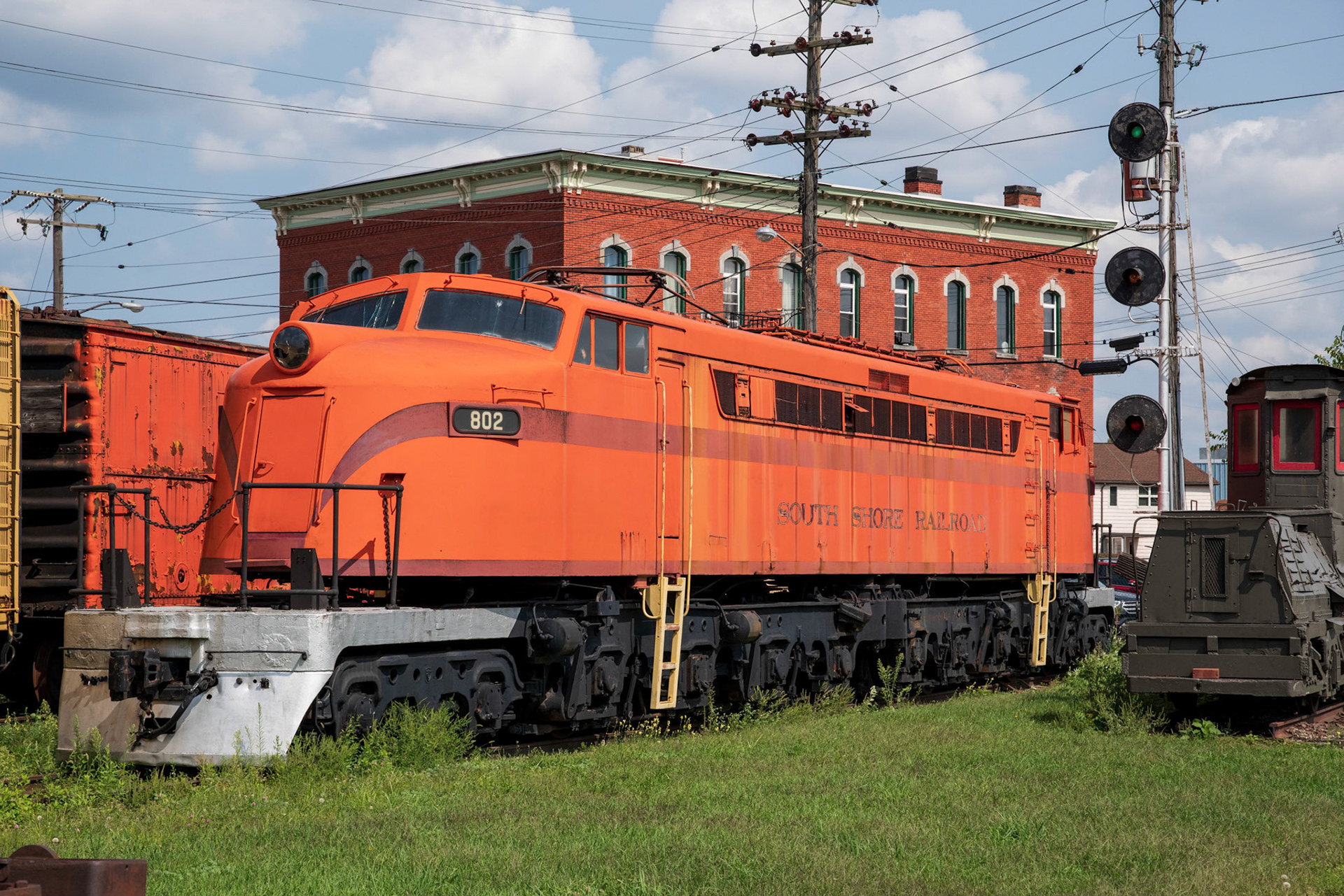
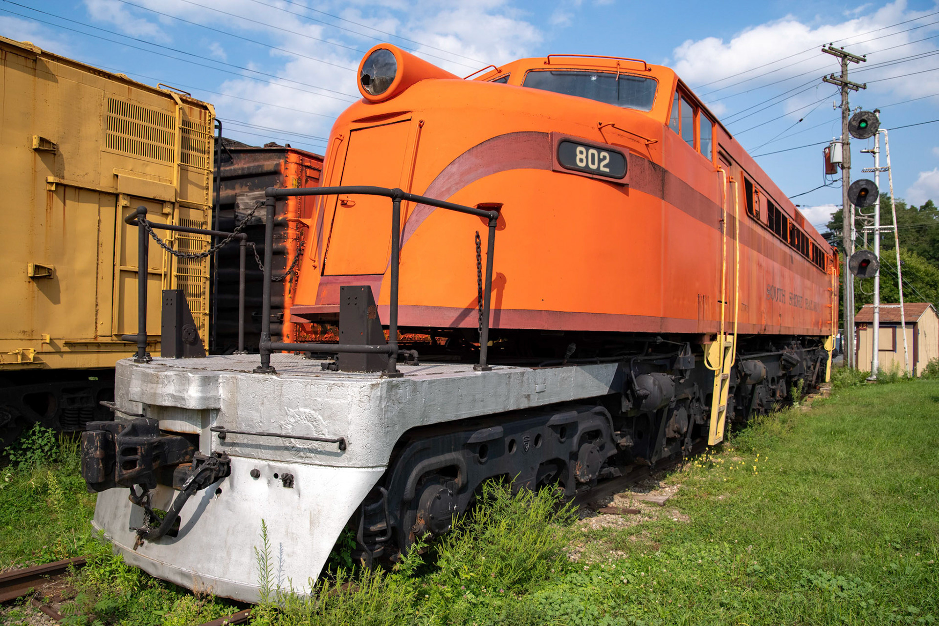
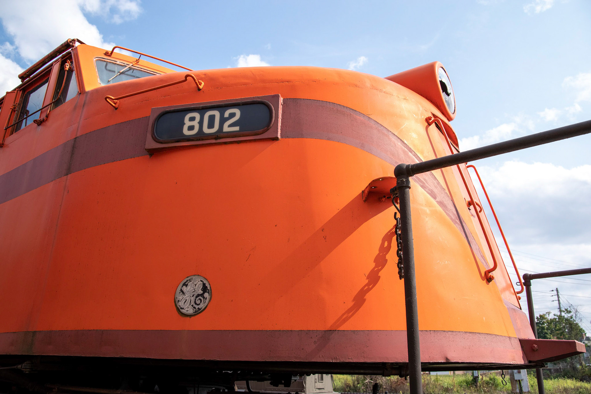
CSS&SB Little Joe 802
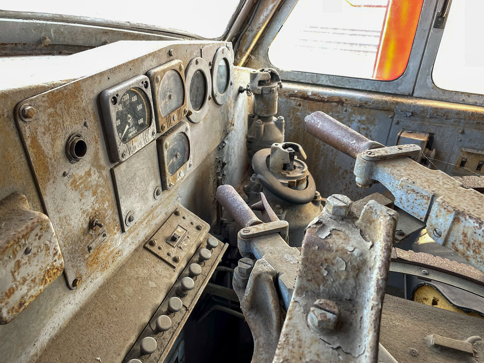
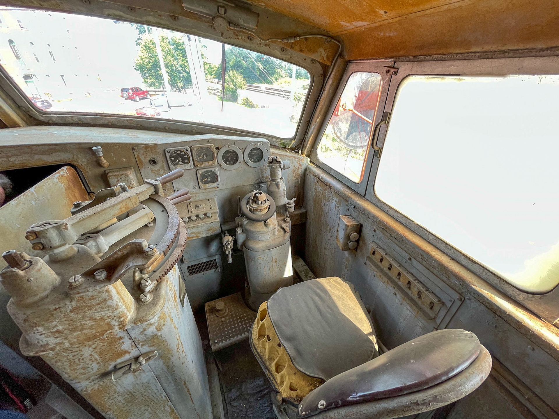
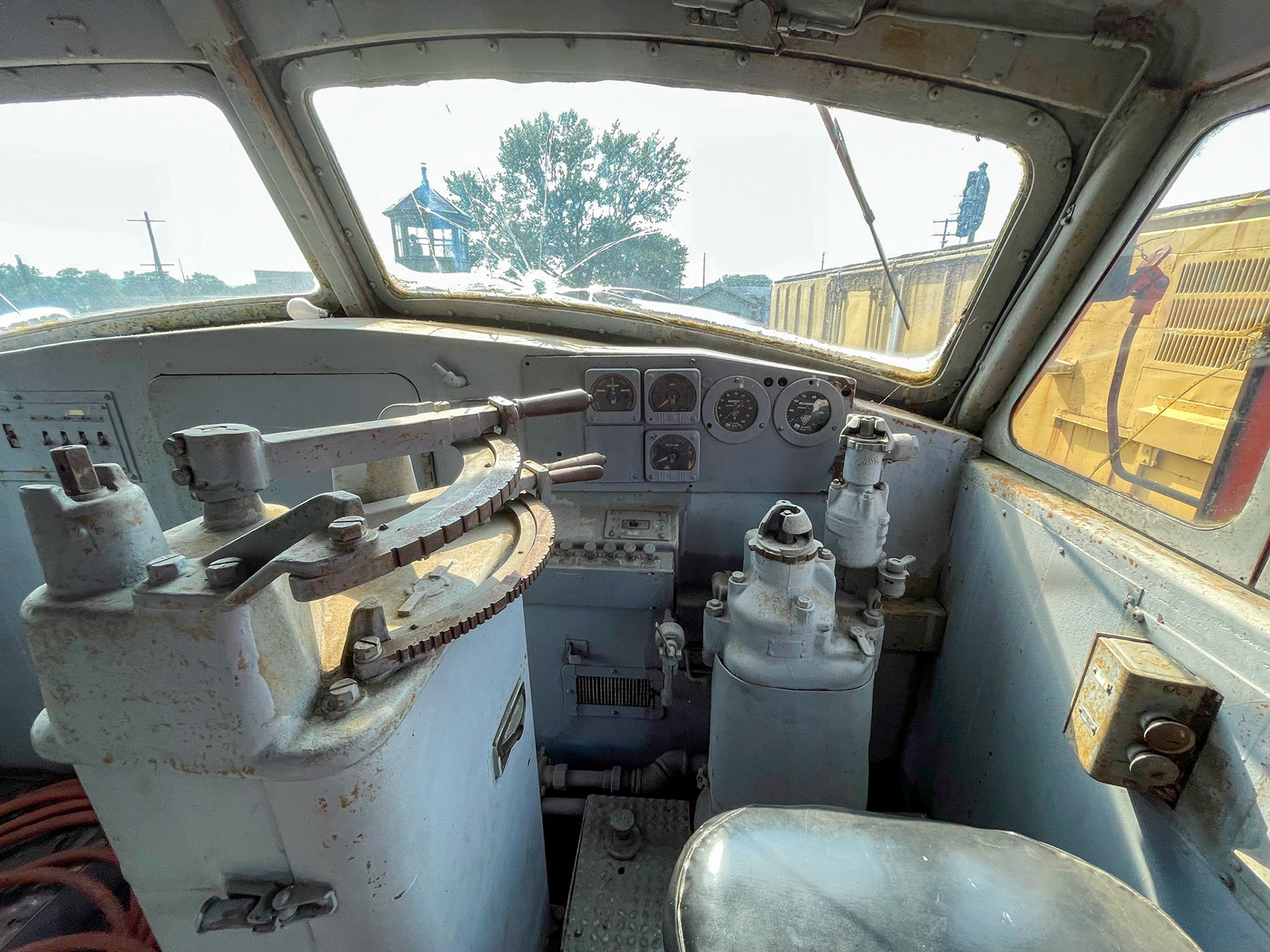
Inside the cab
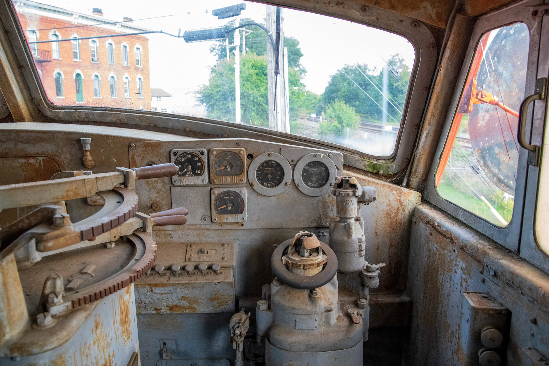
The levers at left are the regenerative braking and throttle controls. Air brake stand in the middle.
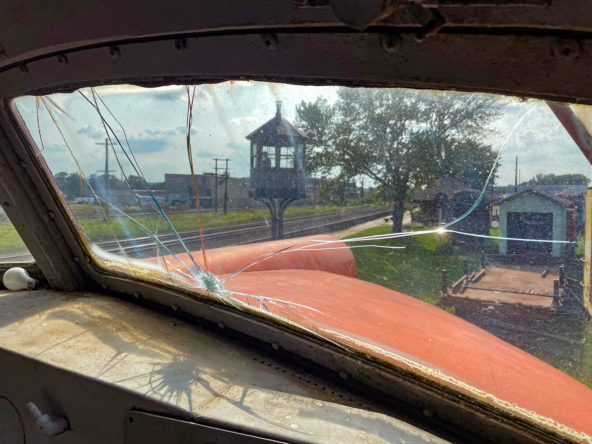
View west
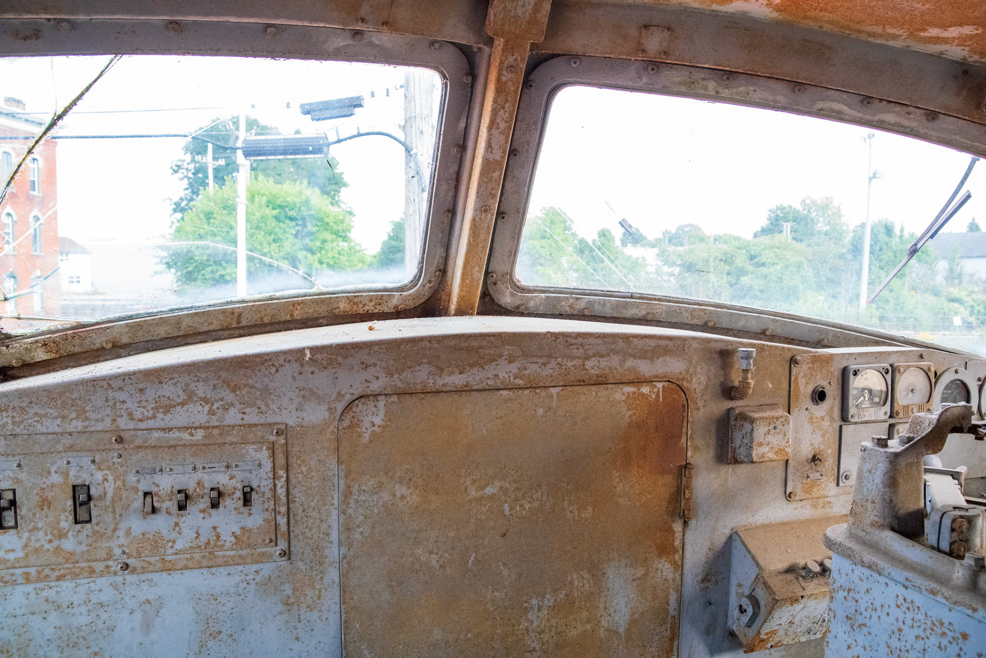
View east from the other cab
Fireman's side
Engineer's side
Fireman's side
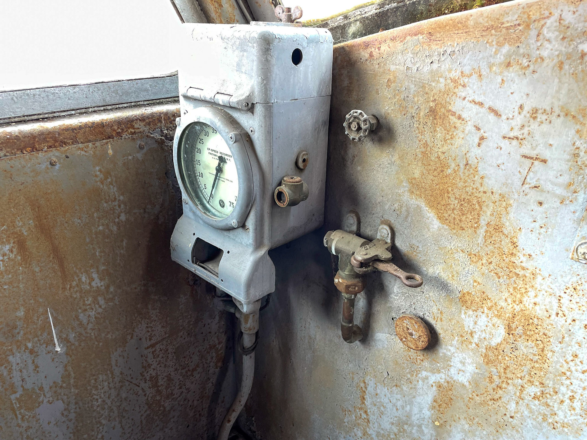
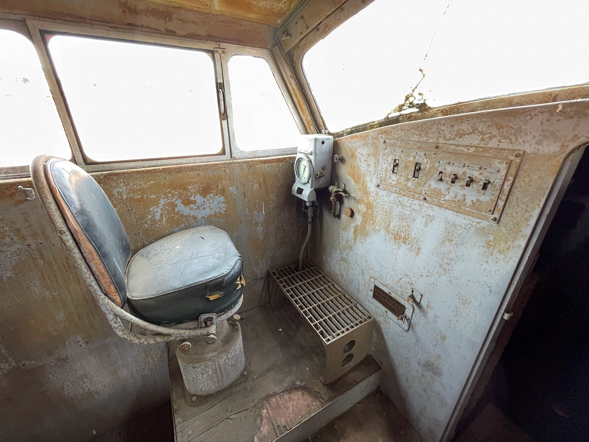
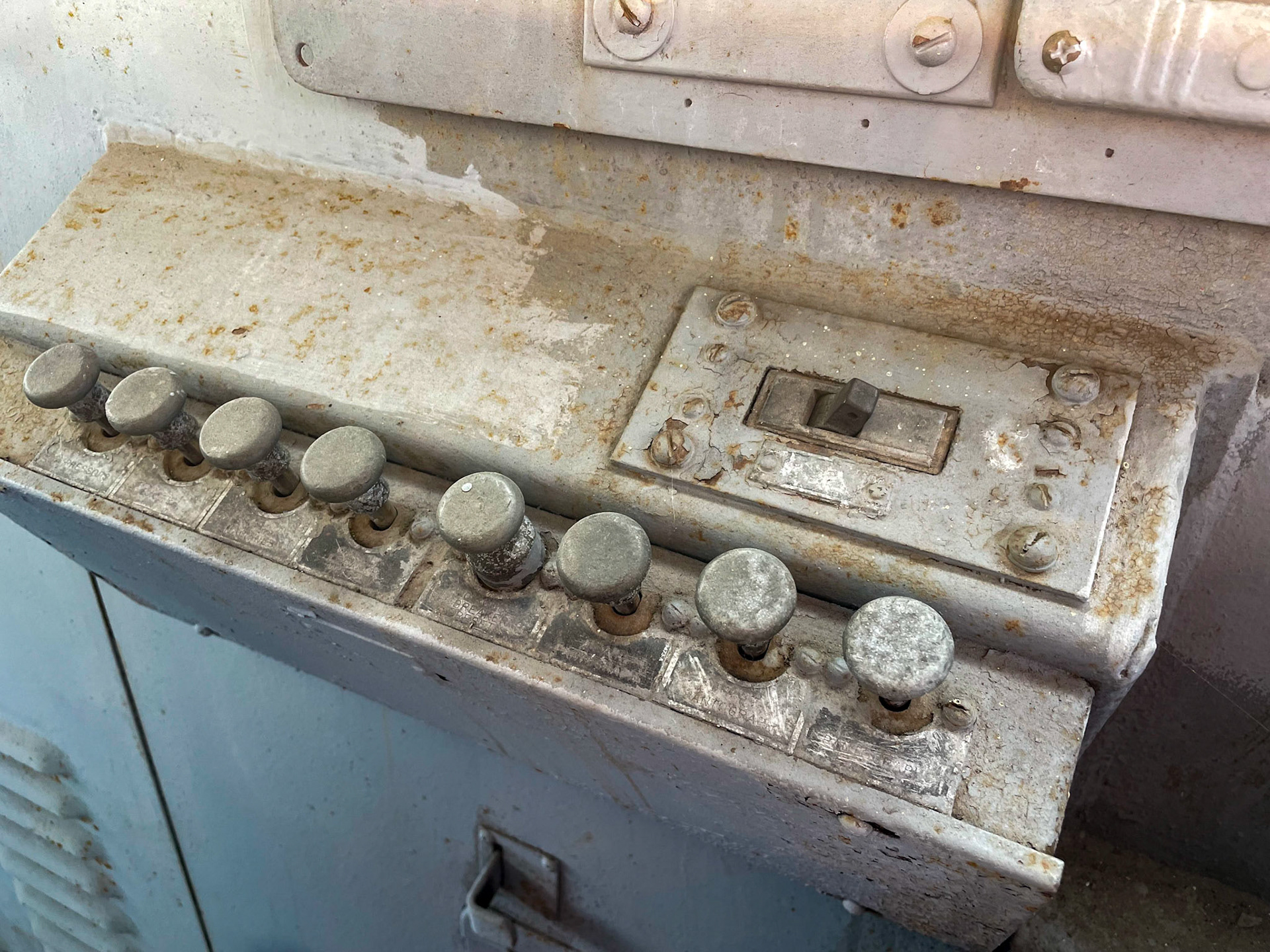
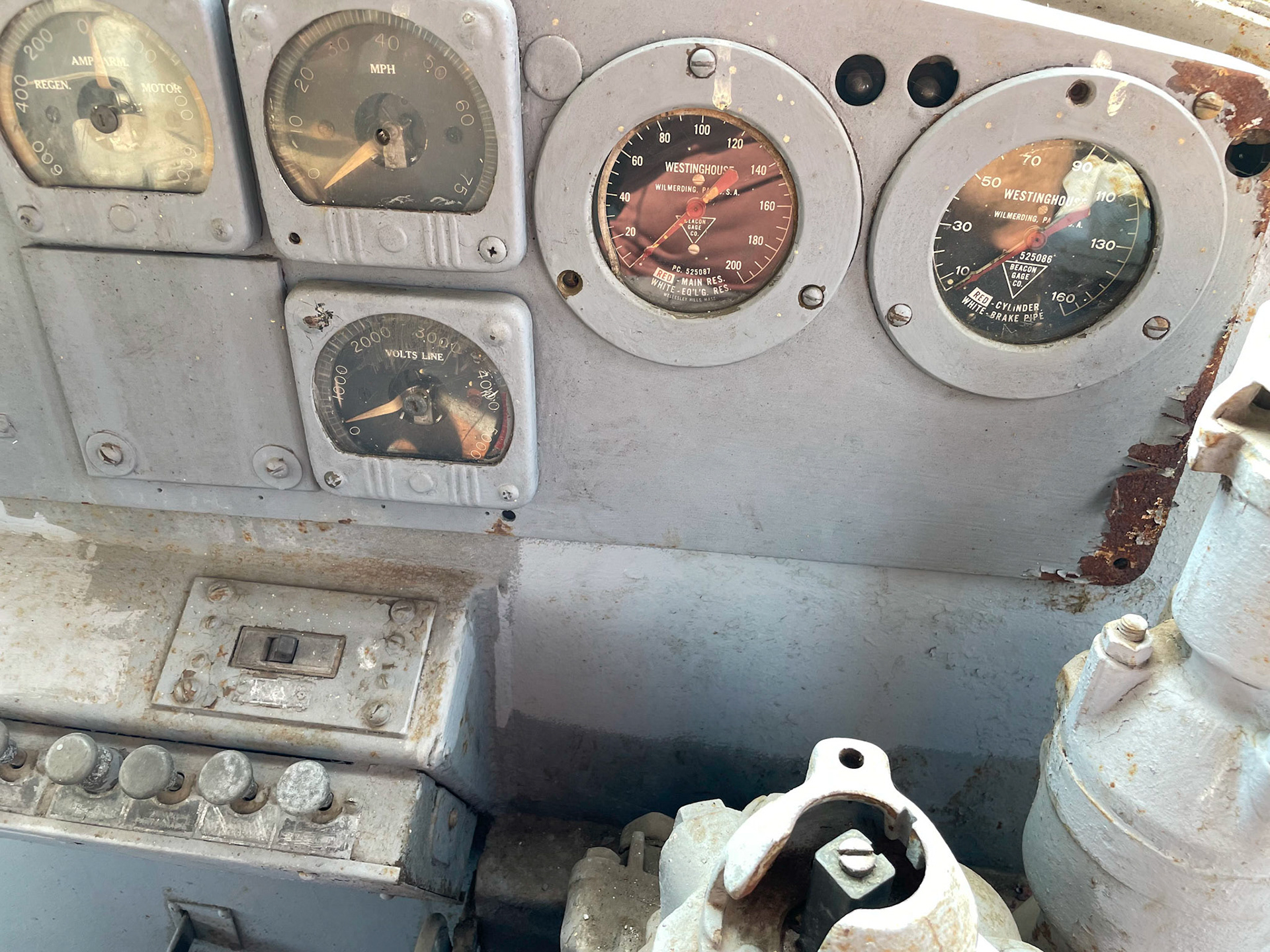
Seat and controls
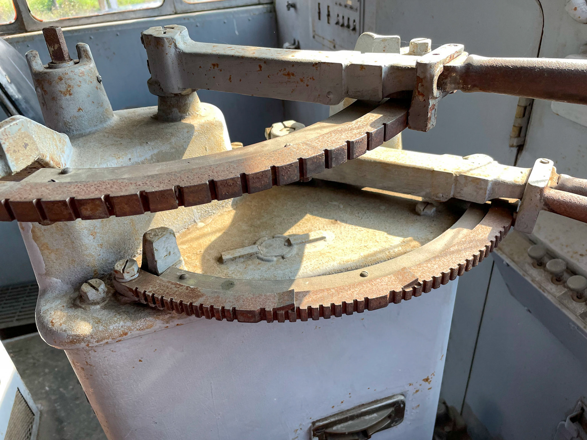
Throttle and regenerative brake stand
Cab view
Under the hood
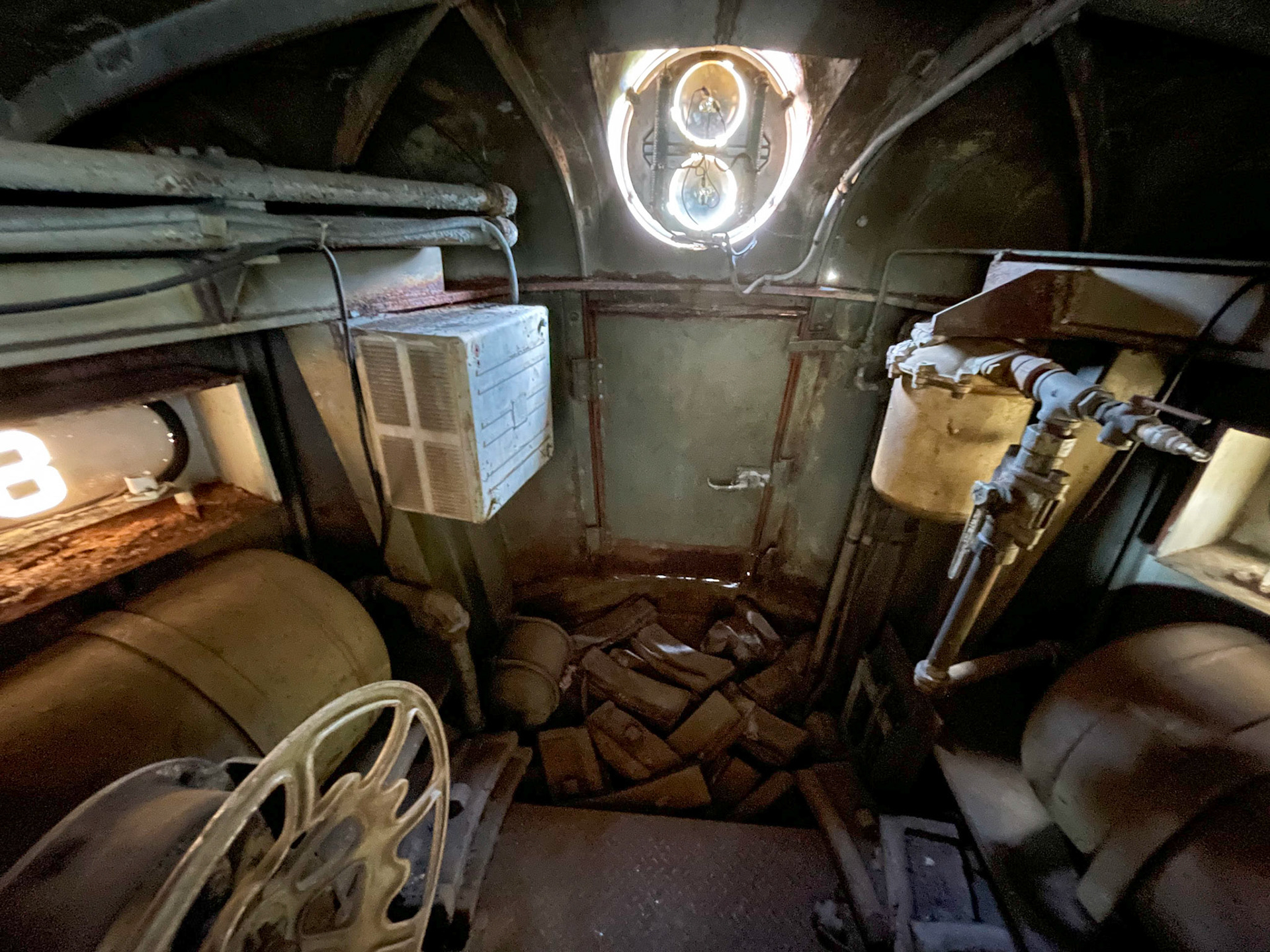
Lots of room inside the nose.
The Joes were powered by 1,200v D.C. in the case of the South Shore units, and 1,500v D.C. for the Milwaukee Road locos. Since these units used D.C. power transmitted over the catenary, they were internally uncomplicated since the power production and modulation was done by the line side electrical substations. On board the loco it was mostly a matter of stepping down the voltage to 600v D.C. for the traction motors and providing control of the motors. The main carbody contained two sets of large traction motor blowers, air compressors and the transformer and control apparatus. The nose compartments are nearly empty - with only air brake reservoirs and hand brake equipment.
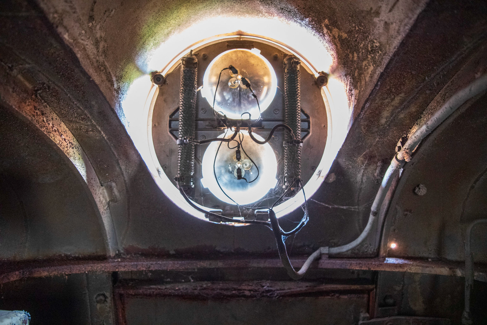
Headlight features two potentiometer coils to adjust voltage

Number board
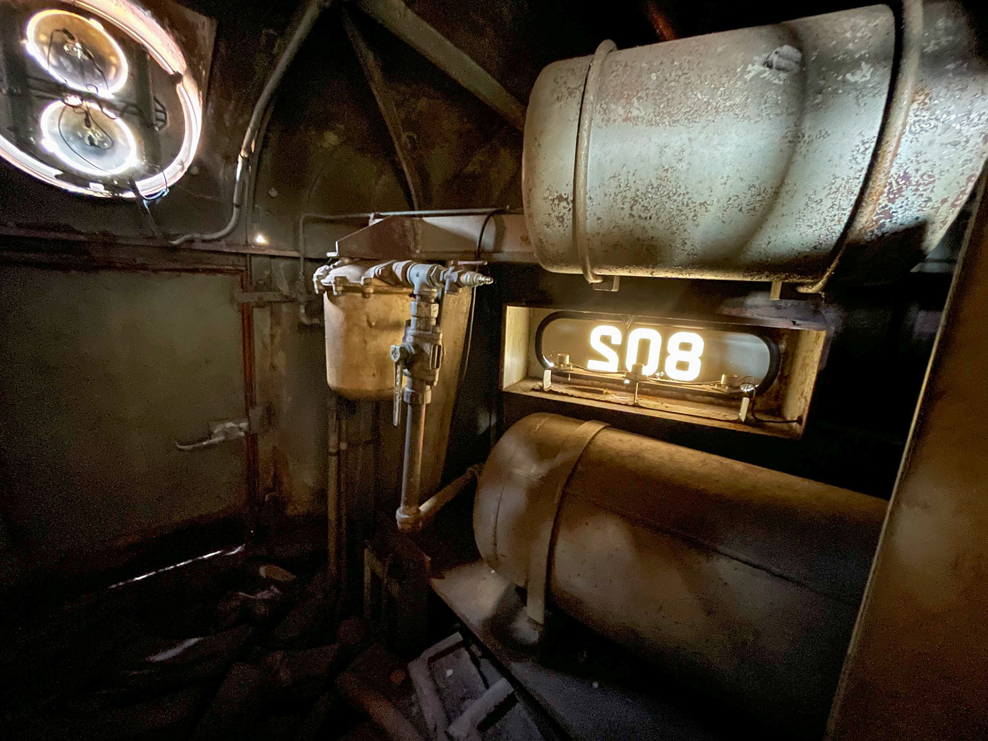
Air brake reservoir above

Traction motor blower and ir compressor
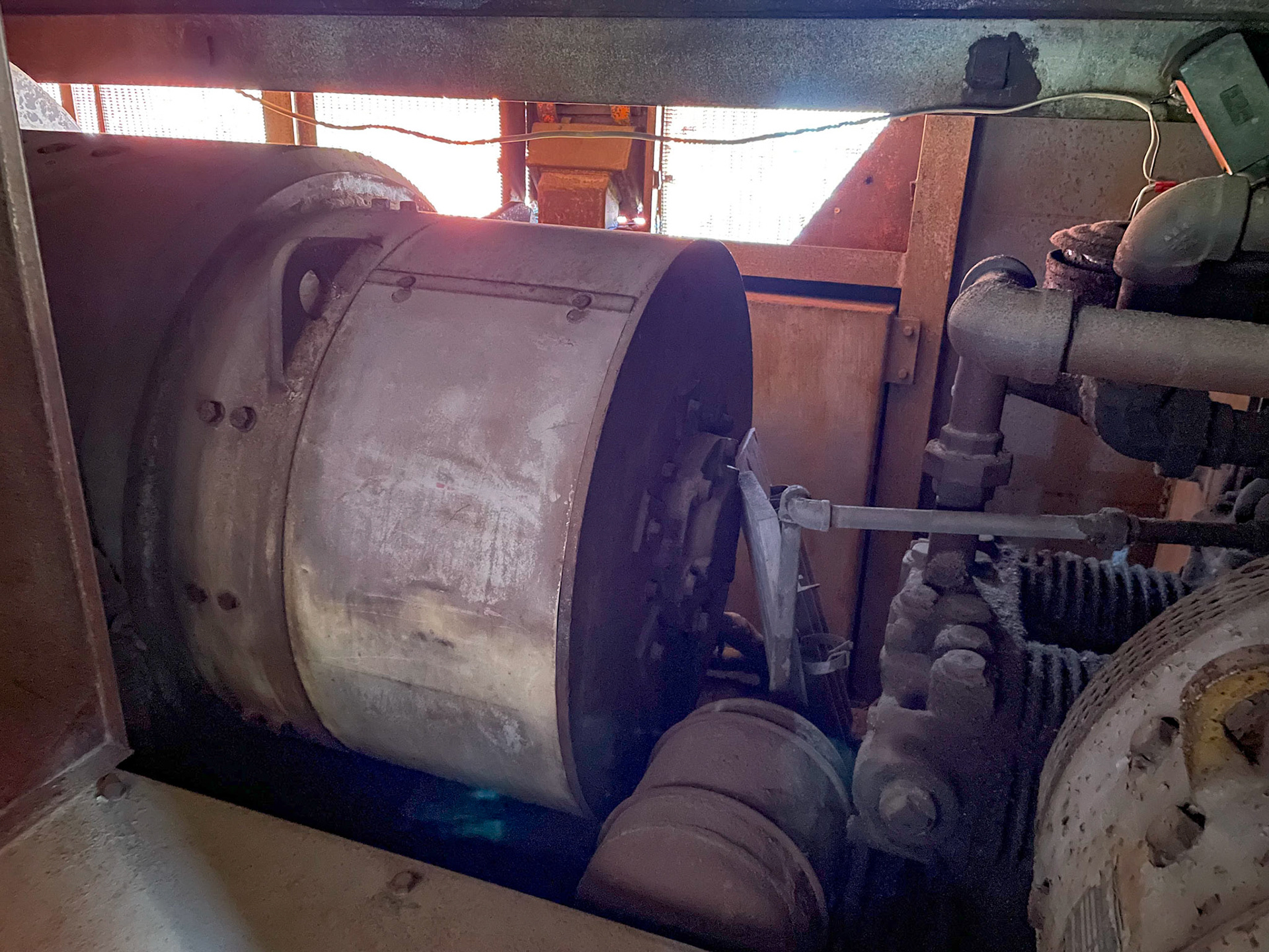
Traction motor blower
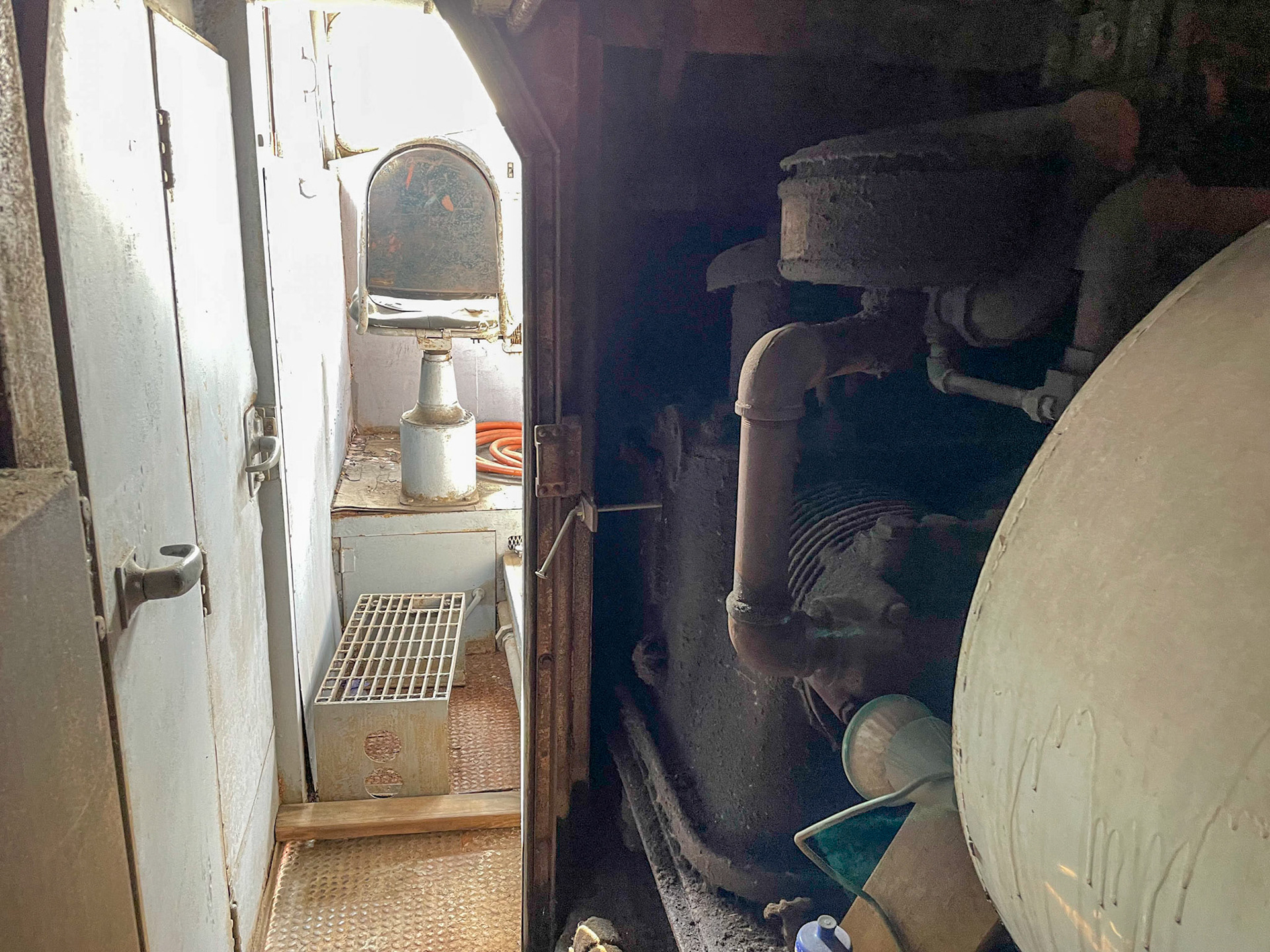
From inside looking towards the cab
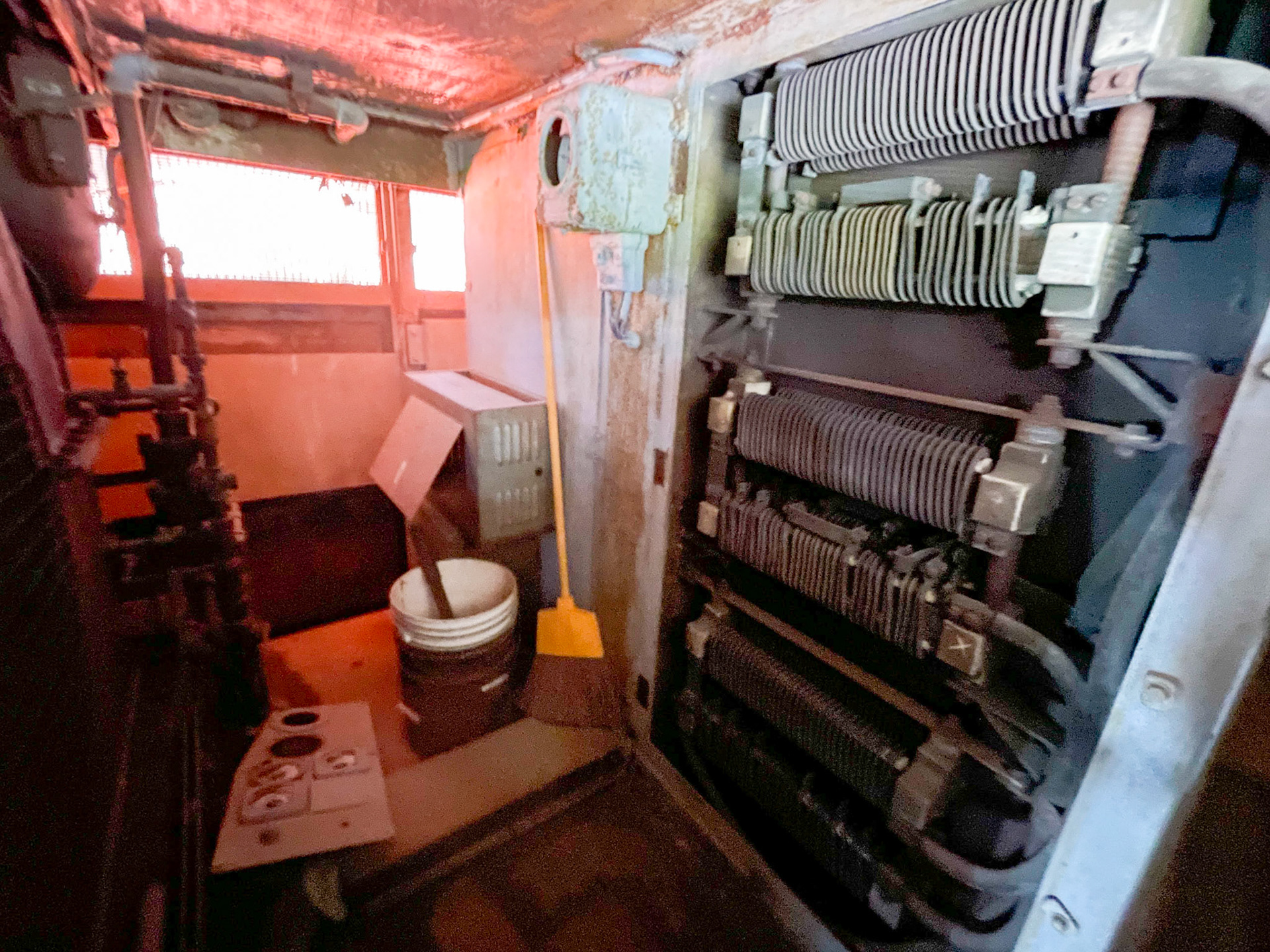
Control apparatus
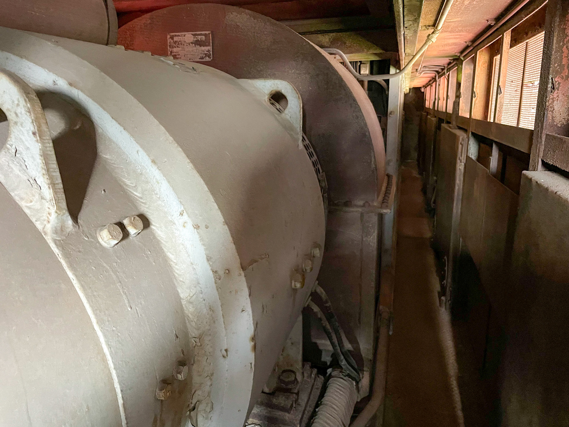
Traction motor blower motor
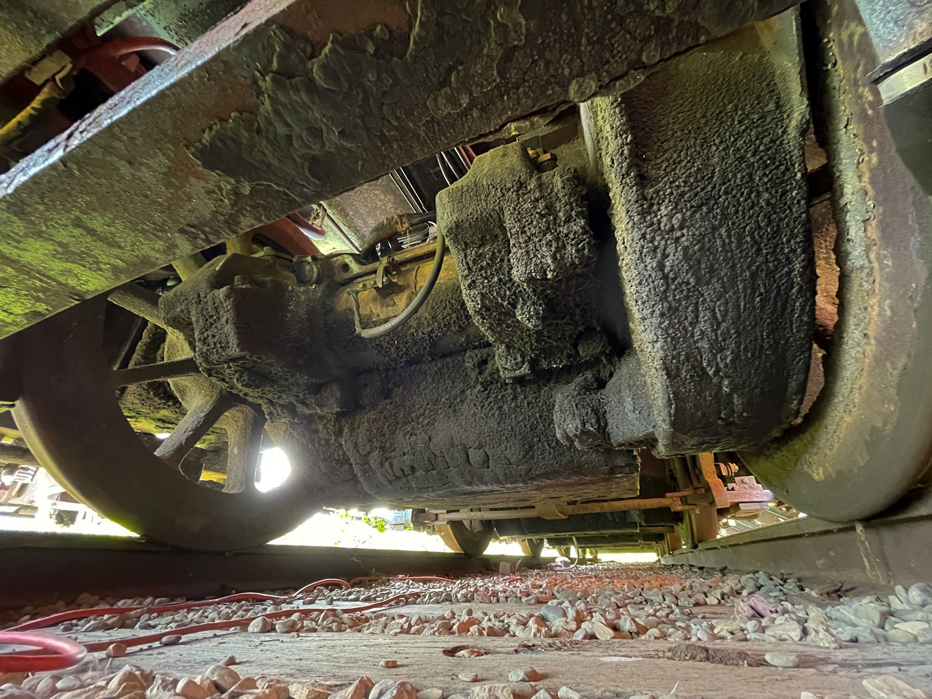
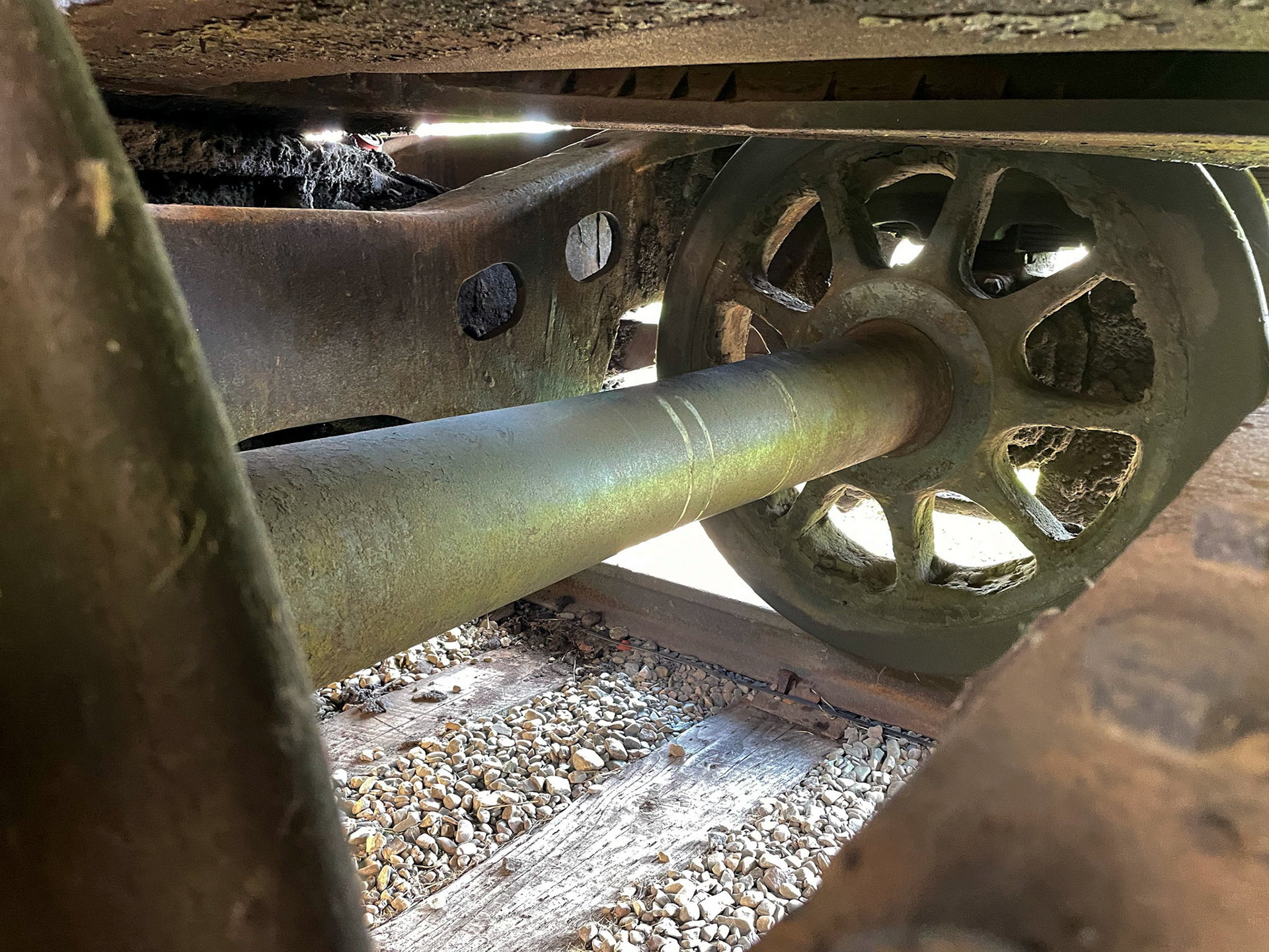
Note that these units were built with spoked wheels.
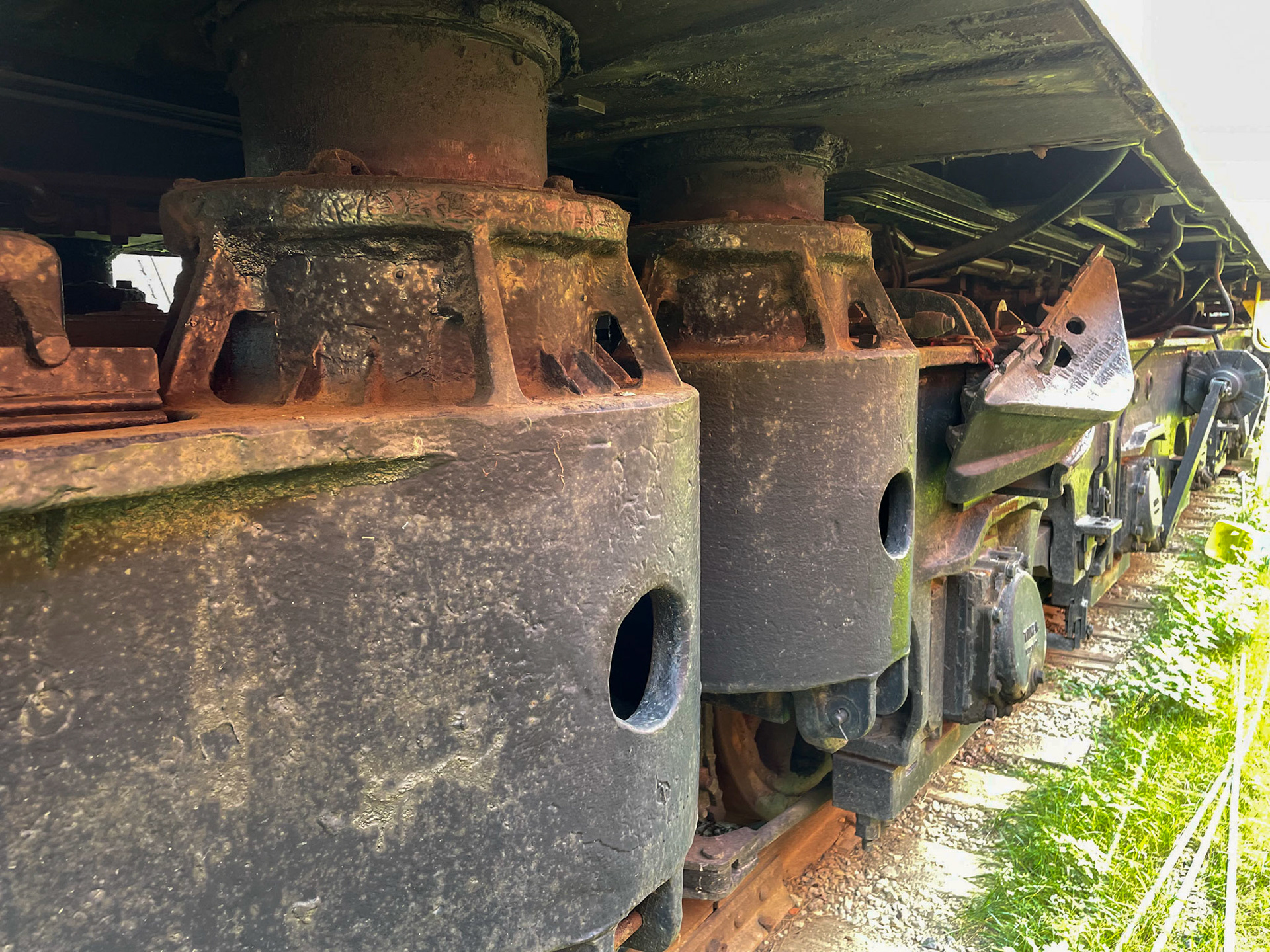
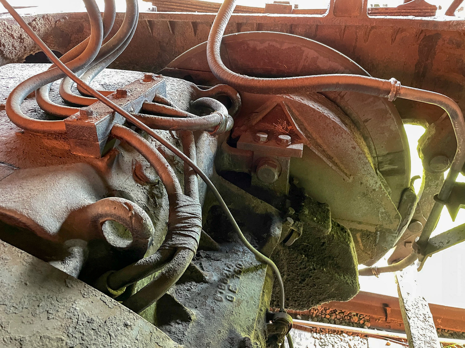
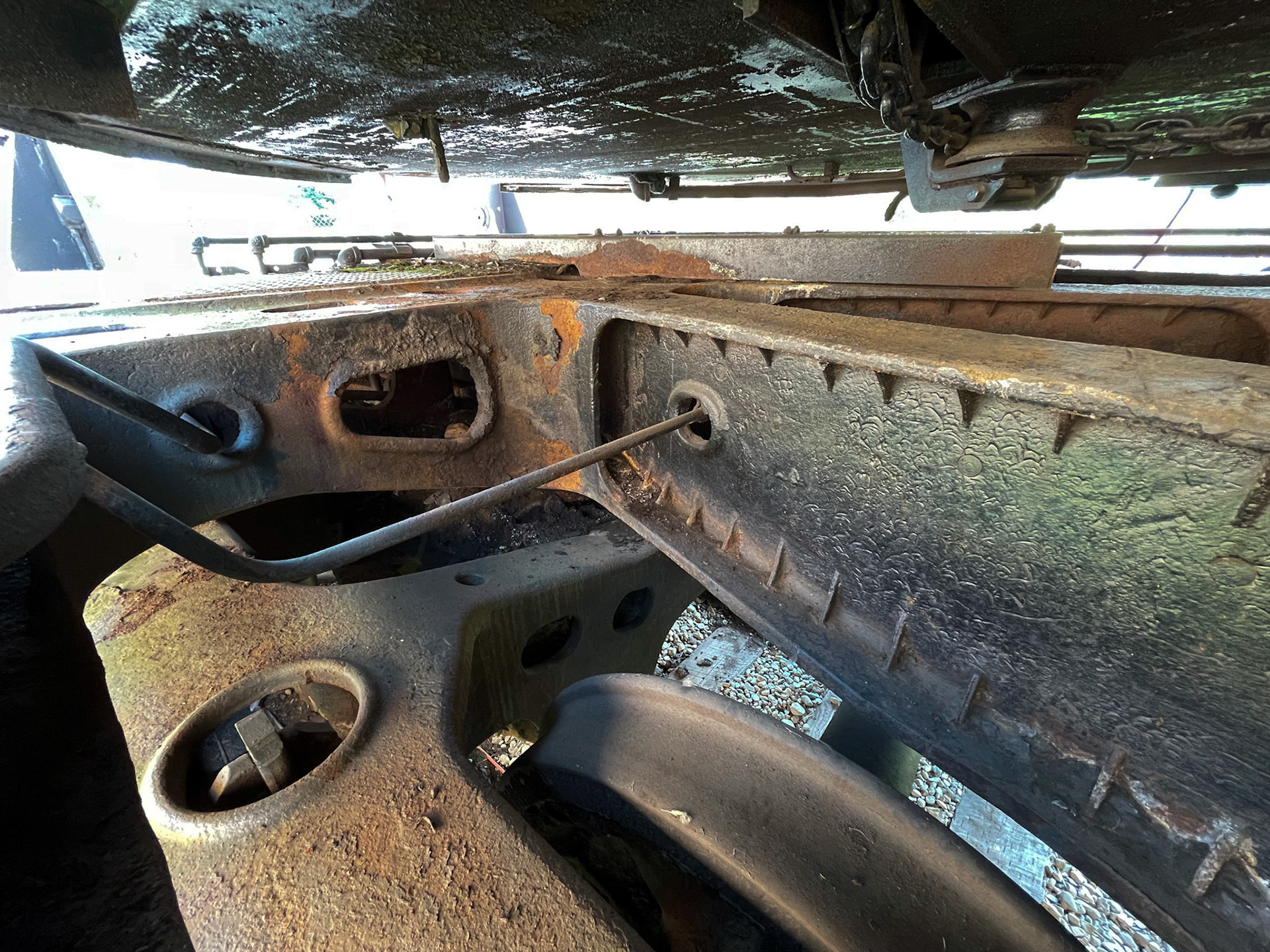
The main running gear consists of the large steel casting for the main 4-axle trucks and pilot, which was half the length of the locomotive. This casting took all of the train buffer stress, and the two truck assemblies were joined back-to-back in the center with a large coupling pin to transfer the buffering forces and keep the trucks aligned.
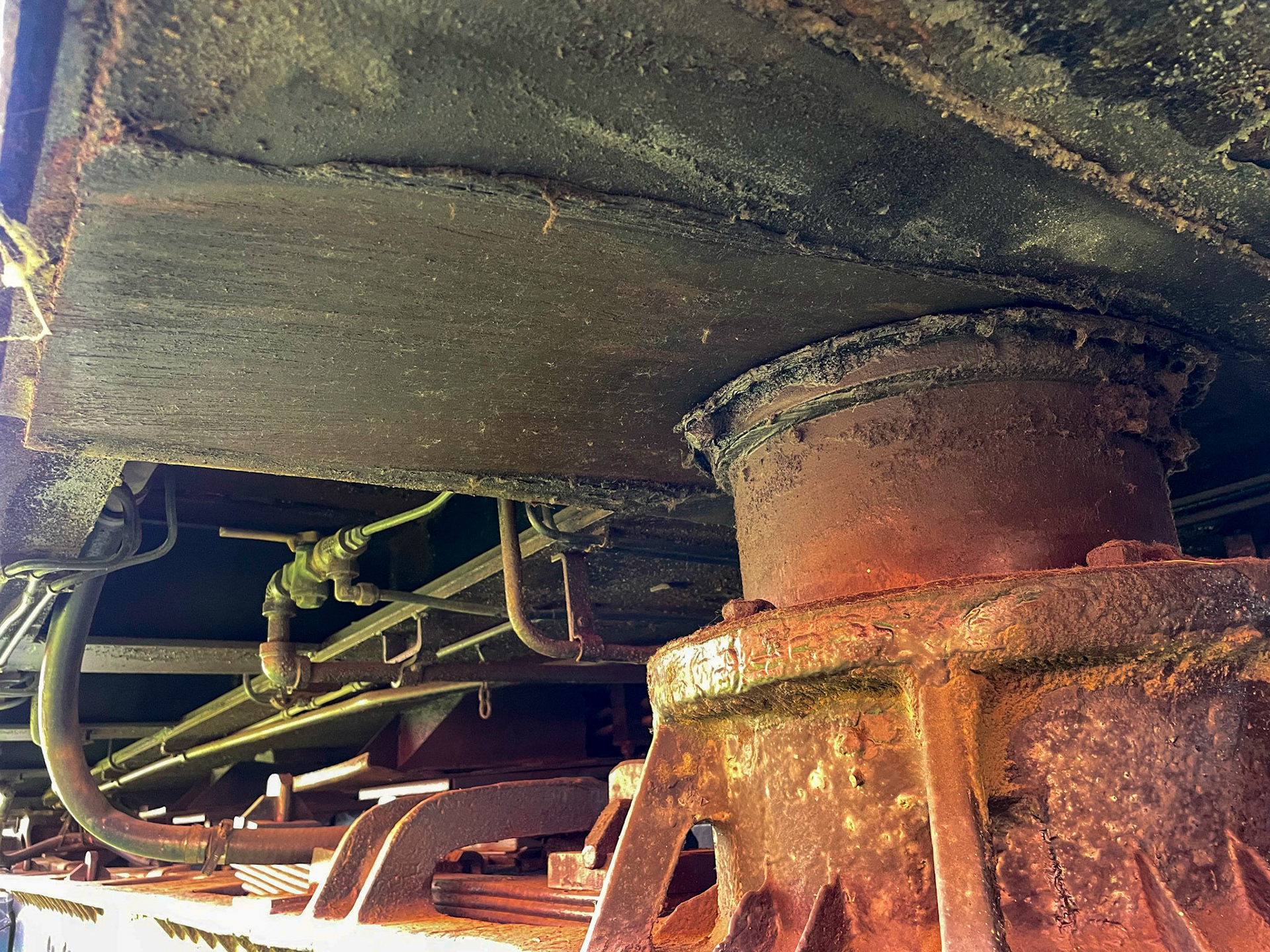
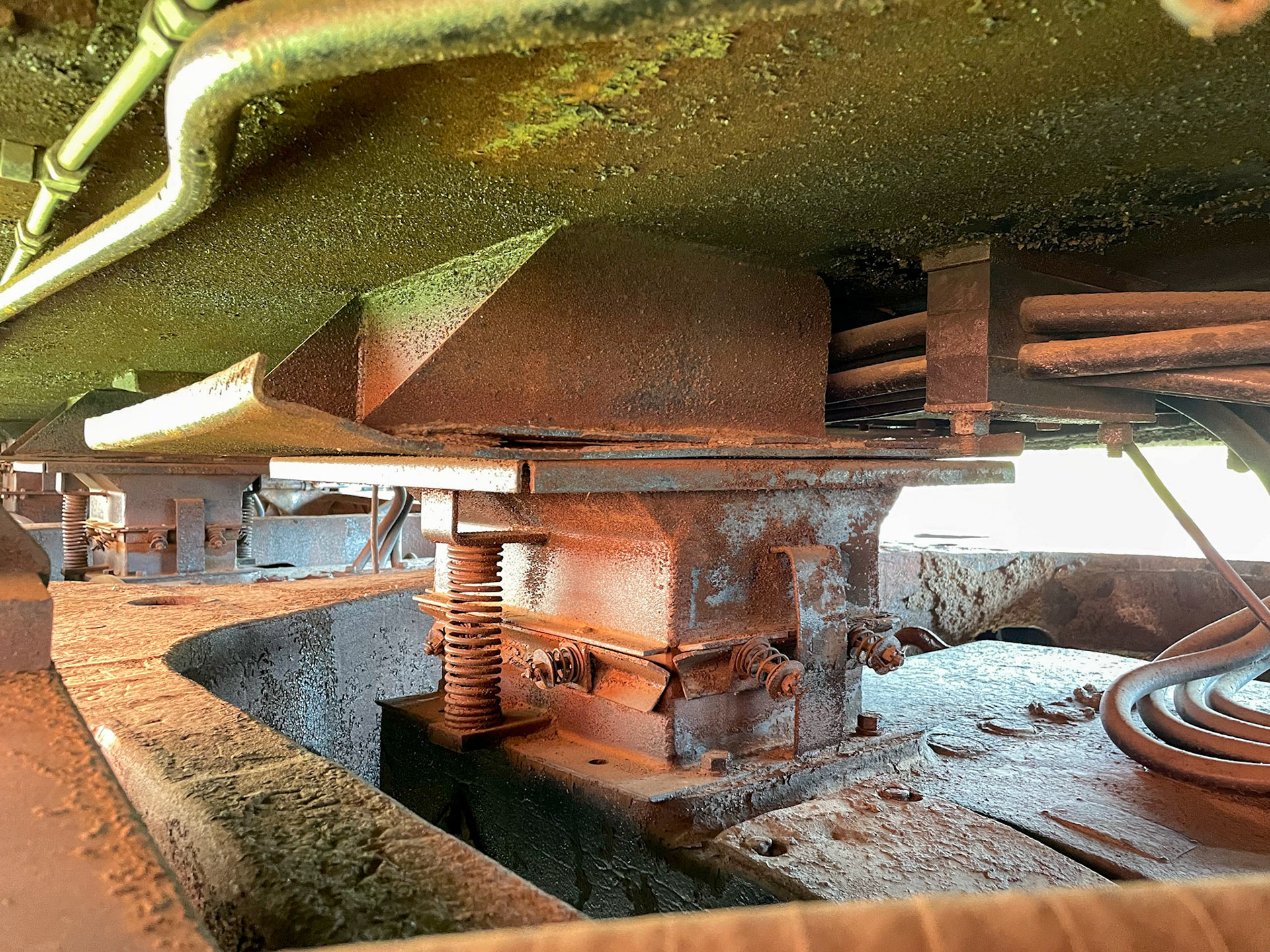
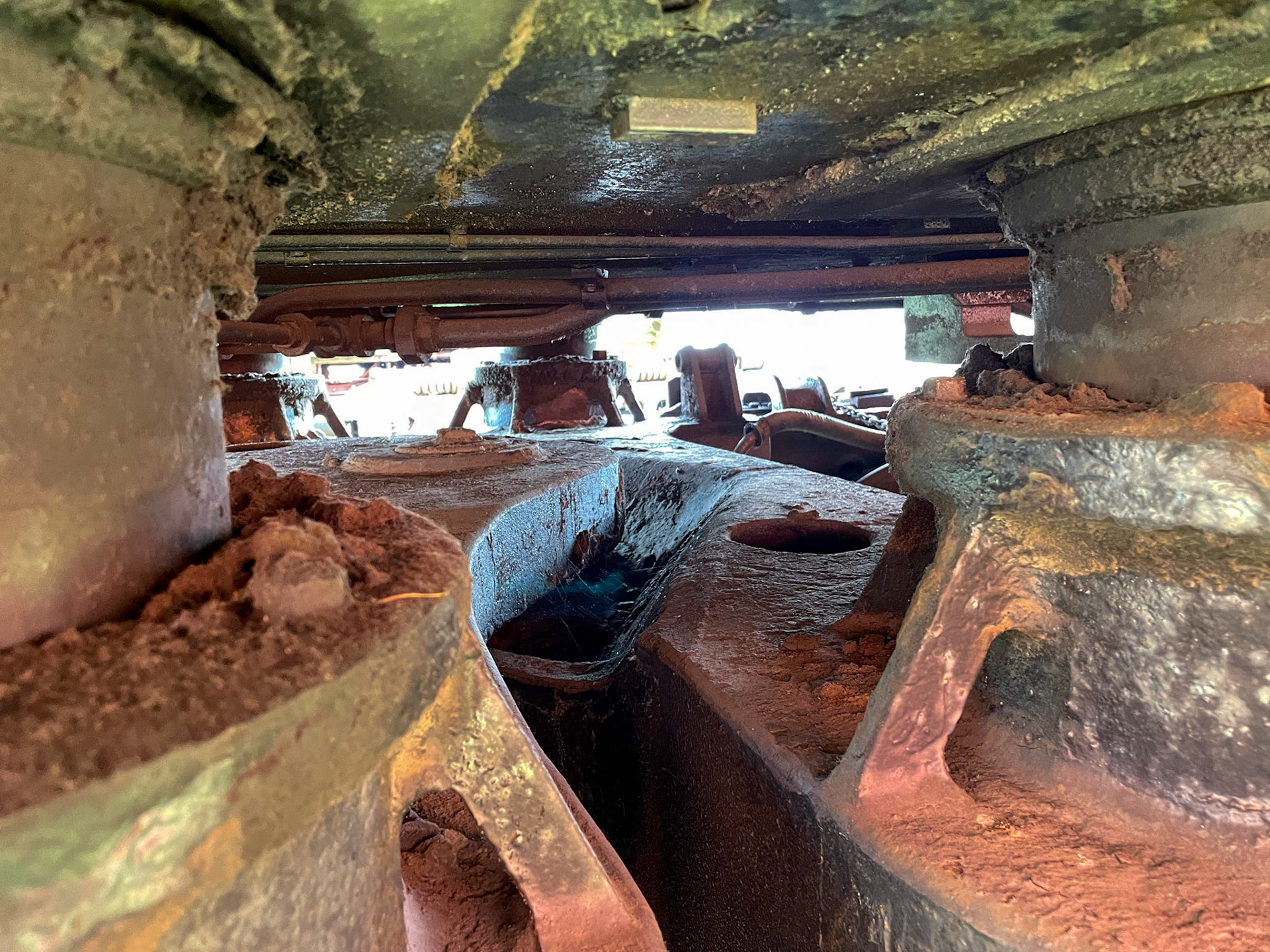
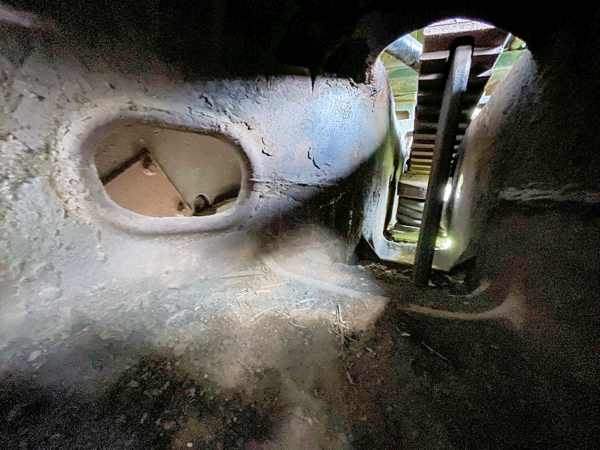
Load pads carried the weight in the middle
Load pads slid as the trucks turned
Traction motor blower feed
Traction motor
Pin linking the frames of the fore and aft main truck frames
Load pads

Traction motor and spoked wheel
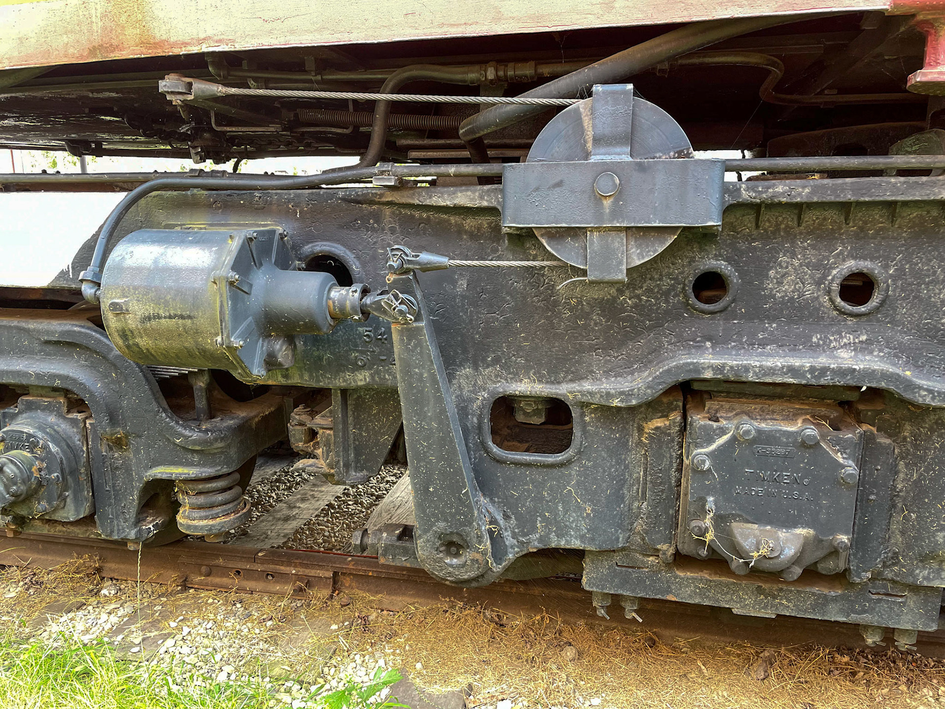
Manual brake linkage pulley tied to brake cylinder and lever
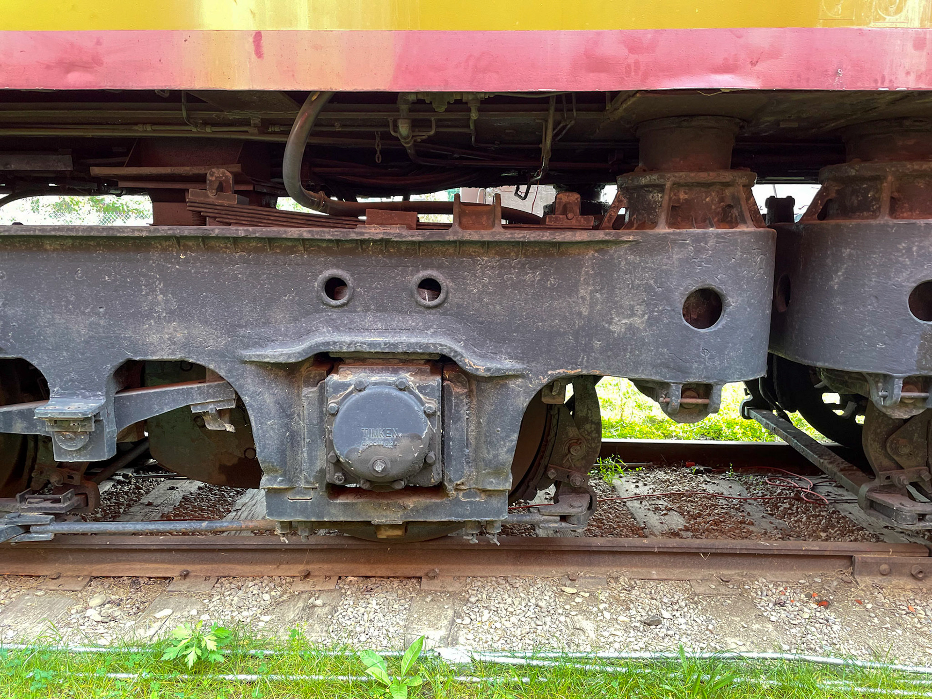
The unpowered 2-axle lead and trailing trucks attached to the large main casting under the pilot, and swiveled independently of the main truck frame. A linkage arm between the lead/trailing truck and the main frame prevented over-rotation and yawing motion of the truck.
Unpowered lead and trailing trucks
Lead truck under the pilot
Inside the main truck frame casting
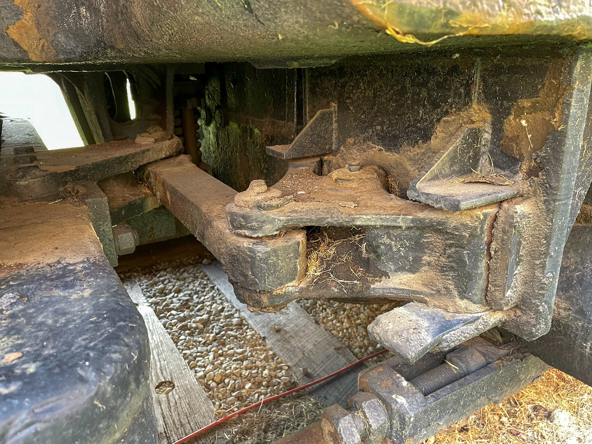
Linkage between the main truck frame and pilot truck
G.E. - we bring good things to life....
Here's a look at 802's sister Little Joe at the Illinois Railway Museum in Union, Illinois by Traveling Tom, and a cab ride in the same unit by Midwest Zephyr Media.